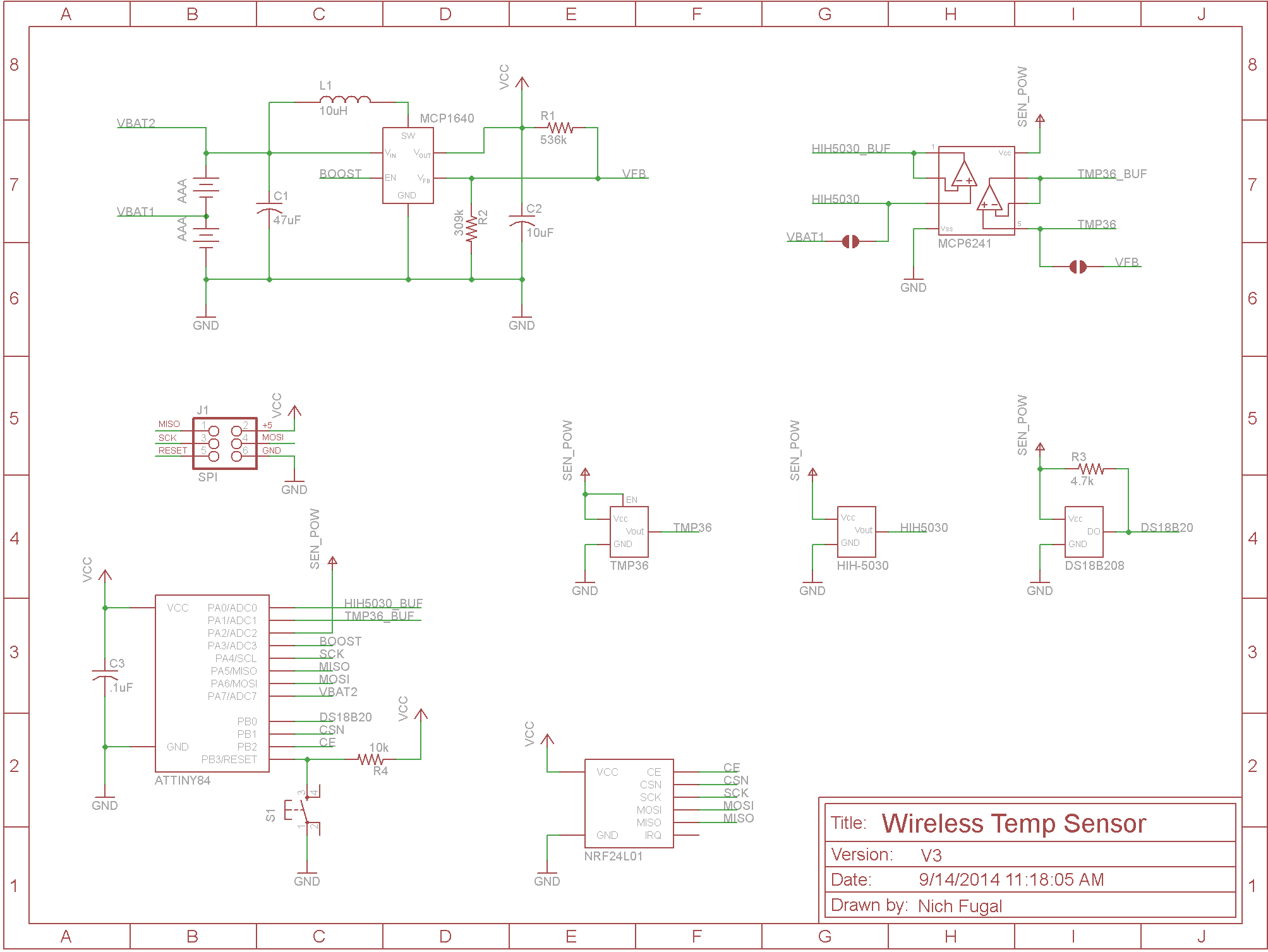
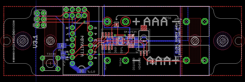
At last we have it. V3 of my wireless HVAC sensor board has been tested and the hardware is done. There were some tweaks to the board over
V2, one to fix a mis-routed trace and several geometric improvements to get it to fit inside an electrical box. And now all is well.
As I said above, the hardware is done, meaning I don't have any (immediate) plans of changing the hardware. The software, on the other hand, is only functional and far from done. I'm hoping the community out there can help to make large improvements over what I've started. Here is a summary of what I've done with the software so far, though there's room for improvement on many of these:
- Software SPI interface to radio with hard coded register configurations
- Communication with sensors
- Breaking various sensor readings into several bytes ready for radio communication
- Power off sensors when not in use
- Power off radio when not in use
- Monitor battery voltage and decide whether to turn off boost circuit (run on batteries directly when sleeping until battery voltage drops below brownout threshold, then keep boost circuit on)
And here's a list of things I hope the software will include:
- uC sleep mode to save battery
- User configurable radio settings (without software reflash)
- User select of which sensors to read
- User select of how often to transmit data
I am putting the board on sale in the Makeatronics store. For now I am only selling the bare PCB (no components or assembly). You can get the bill of materials
here. Hopefully sometime in the next month or two I will start selling the components and assembly as well.
The
design files are hosted on GitHub and are licenced under
CERN OHL v.1.2.
The software is hosted on GitHub under the BSD 3 clause license.


Nich, I've built up one of these boards and have started to test it out. One things that's interesting is when the boost circuit is on, the Attiny takes inconsistent analog voltage reads. It doesn't matter if it's a single reading, or several averaged in a row, readings are inconsistent. When I turn the boost circuit off and run straight off of battery power, it all works like a charm. A multimeter shows a nice stable voltage coming from the boost, and from the temperature sensor. It's as if there are some weird internal oscillations happening when running off the boost. Any ideas? Are you seeing anything like this. I'm considering building up another board to get a second data point.
ReplyDeleteThanks
Interesting... I haven't noticed the same in my testing after I added the op-amp to buffer the sensors. The only things that come to mind are to make sure you put the right capacitors before and after the boost circuit and that the sensors are being powered on properly in software with sufficient settling time after power on. Keep me posted on anything you find. I'll do my best to help troubleshoot.
DeleteCompanies that are fully licensed and certified are also going to employ licensed techs, that have the necessary schooling and qualifications to do repair work. Lastly, companies that are licensed and certified, generally provide customers with full service guarantees (meaning if work is not done properly, they will do additional necessary repairs at no additional charge). Emergency AC Repair Toronto
ReplyDeleteVery useful information you shared. keep sharing.
ReplyDeleteWire Harness Manufacturer in India | Wire Assembly Manufacturers in India
The blog on “Wireless HVAC Sensors – V3 Now Available” highlights innovative features improving energy efficiency and monitoring. A great advancement in smart systems. Explore mlm software in Coimbatore for cutting-edge business technology solutions.
ReplyDeleteInformative update on Wireless HVAC Sensors V3, highlighting improved performance and smart monitoring benefits. The innovation and scalability discussed align well with how mlm software in Coimbatore enables efficient, data-driven business management.
ReplyDeleteThe post offers an insightful look into the evolution of wireless HVAC sensors, especially the improvements in V3 hardware design and power optimization. Features like sensor communication, battery management, and configurable transmission highlight how such systems enhance monitoring efficiency and flexibility in modern HVAC setups . Integrating solutions like Multi MFG further reflects how advanced components can support smarter, data-driven HVAC performance.
ReplyDelete