From a high level, I wanted an interface to a BLDC motor that behaved much like a H-bridge does for a brushed DC motor. The result is a board that handles the heavy work of commutating of a BLDC motor using hall effect feedback. After hooking up power, motor wires and hall sensors, the minimal inputs required to the board are direction (high/low) and PWM. Everything else is taken care of to properly spin the motor. Pretty nifty.


The smart part of this board is that it can act as a SPI slave, keeping track of position of the motor via the hall effect sensors (using a 3-phase adaptation of this quadrature decoding method), or optionally a quadrature encoder (breakout pins included). The SPI master can set a sample-and-hold pin high to tell the Smart BLDC Commutator to sample the current position and get it ready for communication over SPI. Then the master can initiate the SPI transfer at its leisure to read the position at the time the sample-and-hold pin was set. This is particularly useful for closed loop control on multiple motors so that each iteration through the control loop you can read the positions of the various motors at the same instant in time.
Many people will probably ask why I don't offload the control loop itself to the Smart BLDC Commutator, transferring the desired position over SPI and letting the board do the rest. While I have build the board with that possibility in mind, there is a problem when trying to sync multiple motors. That problem is variations in clock speed between multiple Smart BLDC Commutator boards. In college I attempted to build a differential drive robot with a separate uC controlling each wheel and a master uC relaying position commands to them. Because one uC will inherently run ever so slightly faster than the other that means one wheel will spin ever so slightly faster. Therefore, instead of driving in a straight line the robot would drive along an arc. To fix the robot I had to disable on of the uC's and add a lot of magnet wire to get one uC controlling both wheels.
Enough overview. Let's dig into the hardware.
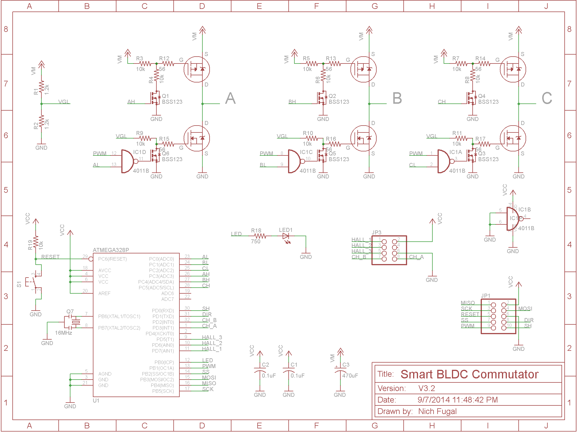
At the heart of the Smart BLDC Commutator is an atmega328p uC, identical to the one found on the Arduino Uno. For easy compatibility with the Arduino IDE, I have a 16MHz external clock on board. A reset button is included because I've learned my lesson about not including them while repeatedly disconnecting and reconnecting power over and over again with reset buttonless designs. An LED lives on board for good measure, connected to an I/O pin to be fully configurable.
Each of the three motor wires, lovingly called A, B, and C, are driven by discrete power MOSFETs: a high-side (P-channel) and low-side (N-channel). At any given time during active commutation there is exactly one high-side MOSFET and on low-side MOSFET conducting, but never both on the same motor wire (which would be a short to ground). Driving the gates of these MOSFETs are a collection of small N-channel MOSFETs and voltage dividers which are used to take the low voltage uC signals (3.3-5V) up to higher voltages required for the power MOSFETs (4-18V).
Because the high-side MOSFETs are P-channel the gate voltage is referenced relative to the source (connected to VM). When the source-to-gate voltage is 0 (i.e. the gate voltage is at VM) then the MOSFET is non-conducting. when the source-to-gate voltage is enough negative (i.e. the gate voltage is less than VM) then the MOSFET is conducting. It is driven as follows: when the AH signal (C7) is low the MOSFET Q1 acts as an open switch. This effectively removes R4 from the picture and what's left is a 10k pull-up resistor R3. When the AH signal is high then Q1 acts as a closed switch to ground, introducing R4 back into the picture and creating a voltage divider to drive the gate of the A high-side MOSFET thus turning it on.
The low-side MOSFETs are N-channel and behave more intuitively. The relevant voltage for N-channels is the gate-to-drain voltage and since the drain is connected to ground here then the gate-to-drain voltage is the same as the gate-to-ground voltage. To make the following description less awkward assume that the PWM value is a steady high signal (100% duty cycle), therefore the voltage at the gate of the small MOSFET Q6 (location C6) is the OPPOSITE of the AL signal (due to the NOT portion of the NAND gate). Now the low-side MOSFETs are driven as follows: when the signal on AL is low then Q6 is conducting, connecting the gate of the A low-side MOSFET to ground making it non-conducting. When AL is high then Q6 is like an open switch, so the A low-side gate gets pulled through R9 to the VGL voltage (set by the voltage divider made by R1 and R2) which makes the A low-side MOSFET conducting.
Now a little about that NAND gate, the 4011B. One of my goals was to have a single PWM input to the Smart BLDC Commutator for power control to the motor. The PWM needs to be routed to each of the three motor wires. Instead of having the onboard uC attempt read PWM from the master and then commutate the motor with the same PWM, I routed the masters PWM to all three motor wires. I then ANDed the PWM with the commutated control signals. However, MOSFET driving circuit meant that a low on AL/BL/CL would result in the A/B/C low-side MOSFET conducting, and a high on AL/BL/CL would be non-conducting. This feels backward and is opposite the high-side MOSFETs and made it hard to keep track of what the code was doing. But changing the AND gate to a NAND gate reversed everything and made it all make sense.
As for how all this gets power to the motor, suppose that the A high-side and B low-side MOSFETs are conducting--current will flow from VM (location D8), through the A high-side MOSFET (D7), out motor wire A and through the motor windings back through motor wire B, and then to ground through the B low-side MOSFET (G6) to complete its journey. As the motor turns and is detected by the hall sensors the uC updates which hi-side and which low-side MOSFETs get turned on, keeping the motor perpetually spinning.
 |
| Click on image for animated version. |
To set all the motor control signals (AH, AL, BH, etc.) I wanted to take advantage of port manipulation on the uC in order to quickly change all pins at once. To allow this I made sure that all the signals were connected to the same port on the uC, in this case port C (PC0-PC5). Now to set the signals all I have to do is write a 6-bit binary number to PORTC. For example
PORTC = 0b001010;
sets AH and BL signals high and all the others low.
For the sample-and-hold and direction inputs from the master into the Smart BLDC Commutator, as well as the hall effect sensors, I wanted to use pin change interrupts for maximum speed and code efficiency, so likewise I ensured that all these signals were connected to a common port, in this case port D. In software I set up an interrupt handler to trigger when any one of the above pins changes, which updates the commutation phase and motor position.
The design files are hosted on GitHub and are licensed under CERN OHL v.1.2.
The firmware is also hosted on GitHub but under the BSD 3 clause license. The firmware will be discussed in detail in a coming post.
Smart BLDC Commutator PCBs will soon be available in the makeatronics store for $15.
How can the motor be driven? (pwm/potentiometer)
ReplyDeleteCan I testrun a 2kw motor(just for spin test,other high powered are expensive, if it does i might upgrade the board)
Wen will be the controller or board available.
Thenks :)
The motor is driven with an external pwm source (or optionally on-board pwm with a software modification). 2kw is a lot of power but you should be able to get it spinning under partial load. If you load it too much I think you would fry the MOSFETs.
DeleteThe board is available now from the Makeatronics Store (see link at the end of the post). Just be aware that you need to have your own hall sensors feeding signals to this board.
The version of Smart BLDC commutator now for sale, can this version handle 8-36 V and logic at 3,3 -5 V?
ReplyDeleteGreetings
Hans
Yes, it can. Motor voltage can be increased even further by changing resistor values. There's some equations on the back of the board for determining those values.
ReplyDeleteHowever, higher voltages mean more heat buildup in the MOSFETs, so heatsinks become more of a necessity. As a point of reference, I can run several amps through my motor at 12v with no heatsink, but at 24v the same motor requires heat sinks on the MOSFETs.
Great!
ReplyDeleteJust what i wanted to know. Your controller board seems to be exactly what i need. I'm familiar with power dissipation, heatsinks etc and think i can sort that out. I'll order a couple of boards right away to tests them for our application.
Hans
Hi again.
ReplyDeleteJust received my boards, Thanxs!
Is there a high res image of the assembled board available?
Just to double check component placement...
I can get one and post it on Saturday. I will not be home until then.
DeleteGlad everything arrived in good condition!
Thanx, think i got the parts right, just downloaded the 'firmware' and the CPU seems to work...One thing you have to look over... The pushbutton you provided is to big for the PCB footprint...
DeleteThanks for letting me know about the reset button.
DeleteAnybody who has purchased one of these kits can request a free replacement botton.
Hi Nich.
ReplyDeleteJust started my BLDC commutator and it' seems to work really well with my 'DUNKER BG40x25' BLDC motor when i use the pwm and dir signals. Now i want to get the SPI data back to my master.
You published some code that you state works with an arduino DUE. When i compile on my DUE there are errors complaining about the 'SPCR |= 0b01;' style commands... Is there even a SPCR register on the ARM-architecture in a DUE, are you referring to a Duemile board?
The code compiles nice on a UNO board, i get something back on SPI, but not correct data. I need to find and adjust settings for the UNO.
Maybe it would have been easier using the SPI library after all.
However, looks like you have created a great BLDC board, THANX!
Hans
Sorry for the delayed response, I hope you've gotten it working now. I'll have to dig into why the SPI isn't working on the Due. This is the board I developed everything on, so it should work, but apparently I've missed something.
DeleteHello,
ReplyDeleteI would like to know if this board could handle 85W motor (I can put good heatsing on). It is 7.4V at 15A max. Also I wouldn't use the hall sensors but control the motor with encoder and 3 sinus waves similar like a brushless gimbal motor, will that work ok? I don't know much about electronics..
Properly heat sinked these components should handle your requests just fine. However, my hardware is not set up to be able to run 3-phase AC waves through the coils. The same PWM signal is routed to each coil, what you're looking for would require separate PWM drives for each coil.
DeleteDo you absolutely need the 3 sine waves? It's perfectly acceptable to drive with square waves. The benefits of a sine wave are constant torque throughout the cycle and lower noise. There may be a few other advantages, but that's all I'm aware of right now.
OMG!
ReplyDeleteJust what I needed! Nice project !
Thanx !
Glad you like it! Feel free to ask questions or post updates as you go along.
DeleteI got my SmartBLDC boards running, but there seems to be a difference in performance if i drive the motors 'Forward' or 'Rewerse'. When speed in reported with negative value it work and sounds nice, in opposite direction, the motor tend to get stuck at start, sounds strange and doesn't reach full speed/power.
ReplyDeleteThe motor is a DUNKER 40x25, similar to this.
http://www.dunkermotoren.com/data/technical_data/motors/pdf/BG42.pdf#page=1
Has anyone else seen this issue?
Regards Hans.
I've noticed in my Turnigy motors, but to a lesser extent than what you describe. I don't know exactly why this is, but here's some thoughts:
Delete1) The hall effect sensors are not "centered" with respect to the stator.
2) The spacing of the magnets on the rotor is uneven and favors one direction over another.
3) There could be a bug in the code, or inefficiency where it takes longer to execute code in one direction over another.
These are just theories. But since it's only a small influence on my motor and it sounds like a bigger deal on yours, I'm leaning toward 1) or 2).
hey,
ReplyDeleteThanks for an exelent design ,)
I am working on a electronic school, and we might be interested in using your boards.
As i understand your license we can use your design files to get pcb's with our school name on them, as long as we still have your link/name on them also?
best regards
michael
That is valid under the licence. The main things are attribution (name/link) and keeping the original licence for any derivative designs. So you can't make a change and then have it be proprietary.
DeleteHi,
ReplyDeleteNice Work
i have some doubts
AH and AL is inverse, right?
Why you used three inputs for Q6, as we can use one also that is AL?(like AH)
I haven't been thinking about this design for some time now, so it will take some time to get back up to speed. But as a first pass I think you're right. AL should always be the inverse of AH so could be exactly AH passed through a NOT gate. That would require another IC which is maybe why I didn't do it in the first place since I had available outputs on the micro. Or it could be that I didn't think of it at the time.
DeleteI haven't been thinking about this design for some time now, so it will take some time to get back up to speed. But as a first pass I think you're right. AL should always be the inverse of AH so could be exactly AH passed through a NOT gate. That would require another IC which is maybe why I didn't do it in the first place since I had available outputs on the micro. Or it could be that I didn't think of it at the time.
DeleteHello.
ReplyDeleteI'm trying to understand if it suits me or not.
I want use it to drive kollmorgen frameless motor RBE 0451, it's frameless torque motor with any sensors and encoders, just stator wiring with 3 lead wire and rotor with magnets.
Problem they nowhere write in their documentation motor power voltage, instead there is such table:
Current at Cont. Torque: A-11.7Amps B-6.20Amps C-17.1Amps
Motor Resistance: A-0.757Ohms B-2.78Ohms C-0.366Ohms
I.e. there is different parameters for each wiring. And as i remember from electrotechnics i can calculate voltage:
A-8.86V B-17.24V C-6.26V
I.e. all are different and B is very different
What should i change on this board to drive this motor? Can i do it?
Sorry, i'm programmer, not electrical engineer, so may be my questions looks stupid.
I took a brief look at the data sheet. It appears that A, B and C refer to different winding options (perhaps number of winds and wire gauge), not the three individual phases if the motor.
DeleteAs long as the current delivered to the motor doesn't overheat the MOSFETs on this board it should work fine. These currents are in the range where I would definitely put a heat sink on the MOSFETs.
Hope that helps!
Thanks for response. I.e. i can buy assembled and it will work, right? there 8-36V on your board, what is enough for this motor, right?
DeleteOk, i paid for full assembled board, could i ask additional question? If i'm going change direction or just stop it quickly i need use some resistor there. How to connect it?
Deleteআমি এটা কিভাবে পেতে পারি
ReplyDeletehttp://makeatronics.blogspot.com/p/store.html?m=1
Deleteআমি এটা কিভাবে পেতে পারি
ReplyDeleteHi,
ReplyDeleteI am also designing a BLDC motor driver board for RBE(H)-001-011-B-00.
Could you help me to select MOSFET as I am using ADuM3220 Gate driver.
Thanks and Regards
Kshitij
This looks very nifty indeed! We're looking for a BLDC controller for hoverboard motors: 36V 3 phase, three hall-sensors..... is there any reason to think your board wouldn't work for this?
ReplyDeleteIf you don't need to make one, please buy one. I made this. Getting it to work is quite the work; and before you know it BLDC Controller becomes your main project and hoverboard will be secondary!
DeleteYour BLDC controller worked like a charm. Very nice. https://bimaokai.wordpress.com/2017/02/26/step-8-the-bldc-motor/
ReplyDeleteWould it be possible for you to tell me which frequency is the best? I recognized that only the Duty cycle is relevant, right?
Could you also give me a recommendation which cooling elements i should use for my motors?
I found out around 2 - 4kHz works the best for me. But then I suppose it largely varies motor to motor. But range will be around 1kHz to 16kHz or so. Try it out! xD
DeleteHello, let me ask several questions.
ReplyDelete1. Is the PCB board programmable? and how can I do that? (e.g., tuning some parameters, see the sensor values)
2. can I also order the PCB with hall sensors? if not, can you recommend where can I order it? (I want a PCB that fits for 35mm motor)
3. what components are included in the "PCB + Components" in the Makeatronics Store page?
Thanks a lot
1. The PCB is programmable via a ICSP header provided on the left side of the board. There were significant errors in the control structure, some I couldn't fix and gave up on! So, yea, you'll need to fine tune it. ;D
Delete2. Hall sensors? You want to embed the sensors and mount the motor on the PCB? That'd be a new PCB then. Hall sensor input is given as a header on the top of the PCB tho.
3. I suppose all parts including the MCU, LL FETs, Power MOSFETs, NAND Gate and the reset switch with other passive components are included. ( I am not selling tho, so, not sure! )
Is it possible to order BLDC Commutator from outside USA. If Yes, how it cost total?
ReplyDeleteHello
ReplyDeleteI want to drive 3000 watt motor with this circuit .
230 Vac , do i need to convert Vac in to Vdc ?
I think that your project of the Smart BLDC commutator is very interesting. I like the idea of having one PWM and control the rest with a more direct approach, and using P-channel MOSFET for the HI sides. This is rare and find it simpler than having a boost trap and driving the HI side with N-channel MOSFET.
ReplyDeleteDonald Wright of the Openvolta projects
A smart resource for leaders driving evolution across technology and industry.
ReplyDeleteEnrgtech Electronic Parts
This deep dive into Smart BLDC Commutator hardware is spot-on. Moving away from mechanical brushes to sophisticated electronic commutation really optimizes motor efficiency and longevity. The design considerations mentioned, especially regarding sensor integration and thermal management, are critical for reliable performance in high-speed applications. However, the real challenge always lies in the implementation phase. Finding a reliable PCB assembly manufacturer is essential to ensure these complex circuits are produced without defects. High-quality soldering and precise component placement make all the difference in board-level performance. Great read, and I’d love to see more on power stage optimization next!
ReplyDelete