
- A single input for motor direction
- A single input for PWM (motor speed/torque)
- Commutate the motor windings based on hall sensor feedback
- Keep track of position through hall sensor feedback and communicate position to external microcontroller
- Inputs for optional quadrature encoder
- A "sample and hold" input to save the position at an instant in time into a buffer (for synchronizing multiple motors/controllers)
- Some kind of communication protocol to communicate with external microcontroller
- Works with 3.3v or 5v control circuitry and 8-36v motor power
- As fast as possible using pin change interrupts and hardware communication
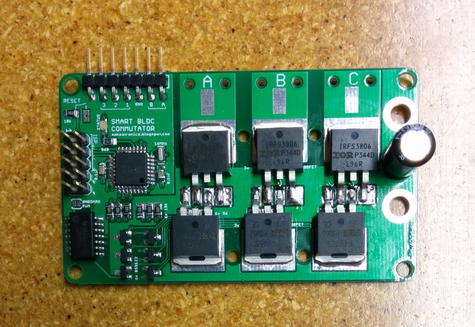
At the heart of this control board is an atmega328p microcontroller running at 16MHz, the same as used on the Arduino Uno, and programming is accomplished via an external ISP programmer. I played around with the idea of using a smaller/cheaper microcontroller, but after including all the features above I ended up using all but 3 of the available pins on the 328. Plus, going with the standard Arduino chip has the benefit of familiarity for me and many others.
Direction and PWM Inputs
A necessary part of any DC motor is that the current direction through the windings alternates as the motor rotates (commutation). The way a typical (brushed) DC motor handles this requirement is via brushes riding on a split ring on the shaft of the motor.
This design makes controlling the motor very easy. Simply apply voltage to the two wires and the motor spins. If you reverse the two wires the motor direction reverses. Then for speed control you add PWM to the motor power.
A BLDC motor has no brushes (by definition) and no split ring to do the commutating. Instead, the commutating is controlled by some kind of logic circuit. This circuit must know the position of the magnets relative to the windings in order to commutate correctly. Also, the majority of BLDC motors have 3 wires coming out of them (3 phase = 3 sets of windings in the motor). Voltage is applied across only 2 of the wires at any given time. Which 2 wires and the polarity of the voltage across them is always changing as the motor rotates. It is the job of the control circuit to do this correctly.

In the image above you can see that there are a total of 6 switches (3 phases * 2 polarities), and for this instant in time voltage is applied across coil A (positive) and coil B (negative). Replace the switches with MOSFETs and you have a basic driver circuit. To get variable speed control you would switch the MOSFETs on and off with a PWM signal at the gate. A total of 3 PWM signals are needed (only one for each coil), the other 3 MOSFETs are plain on or off.
For my control board I wanted to have a single PWM input from an external microcontroller control all 3 coils. I accomplished this with some AND gates on board. The control circuit would set the 6 pins for the 6 MOSFETs, 3 of them are routed into one side of the AND gates (separate AND for each of the 3) and the PWM into the other side of the AND. The outputs from the AND gates are PWM modulated versions of what the control circuit is providing, and these signals are then routed to the MOSFETs.
The direction of the motor is handled by an input pin from an external microcontroller (or switch) to the control circuit. The on-board software then takes care of changing the control signals to reverse the motor.
The choice to have the PWM and direction be inputs from an external source was to keep the control board as close as possible to the way you would drive a typical DC motor. Of course, with a change in software these things could be handled from the control board itself.
Hall Sensor Feedback for Commutation and Position
As far as I know there are 3 ways to commutate a BLDC motor: manually at a given rate, sensing the back EMF in the unpowerd coil to deduce rotor position, and sensing the rotor position with hall effect sensors.
Manually commutating at a given speed is basically the same idea as controlling a stepper motor, but is usually frowned upon in BLDC motors. One of the reasons is that it wastes a lot of energy because the winding resistance of a BLDC motor is a lot less than a stepper motor, so a lot more current flows, generating excess head in the motor and the MOSFETs.
Sensing back EMF is usually what ESC controllers do. They are more complicated with the added sensing hardware, but allow the motors to be cheaper since they don't have to come with sensors built in. They also have the advantage of being able to adjust the motors timing on the fly. This kind of control is good for controlling the speed of the motor at high spin speeds, but is not a good solution for low speed/high torque applications. This control board does not have the necessary hardware built in to run in this mode.
Hall sensors are generally more expensive and the motor timing is hard set, but they give good low speed performance. This is the intended operating mode for my control board. There are many good articles available on the internet that explain how to commutate the motor once you have feedback from the sensors. I'll leave the explanation to those other sources and present here only this handy diagram that shows the polarity of each of the 3 motor phases with respect to the hall sensor feedback (referred to as switches in the image).

Turns out that finding motors with integrated sensors is hard to do unless you're looking for industrial sized motors. There are a few intended for RC cars, but they have a low pole count and are not suitable for precise positioning. In lieu of finding good sensored motors, I decided to add sensors to my own motor. Turns out adding sensors to an outrunner BLDC is pretty straight forward (see my blog post here for more info). Plug these sensors into the control board, make sure you have the 3 motor wires plugged in in the proper order (trial and error is a good approach), and set the timing appropriately and you have all the makings of a sensored BLDC driver.
One thing I've found particularly exciting is that I've come up with a way to use the hall sensor information to simultaneously keep track of the position of the motor. It's only as precise to 1/(number of magnets * 3) revolutions, but if you have a high enough pole count on the motor you can get away with using the hall sensors in place of an external encoder. That is a significant cost saver on position feedback. In case a higher resolution is needed, there are two additional pins broken out for the A and B channels of a quadrature encoder, and the software can be updated to monitor the position of the encoder rather than the hall sensors.
As for how the position feedback from the hall sensors work, it is very similar to the method I presented in my quadrature post. If you haven't done so already, I suggest you go and read it since I'll only talk about the differences here rather than going through all the details again.
The operating principle of reading quadrature was to use the previous and current states of the two channels combined together to become the index for a lookup table. The value in the lookup table would then be added to the position to either increment it, decrement it, or do nothing. In the quadrature case the index value is a 4-bit integer (2 bits for the previous state of channels A and B, 2 bits for the current state), so the lookup table is 2^4 = 16 elements long. Using the same thought process, it's possible to build a lookup table using the previous and current states of the 3 hall sensors. Since there are 3 sensors, the index value becomes a 6-bit integer and the lookup table becomes 2^6 = 64 elements long. It's a lot more work to fill out a 64 element table as opposed to a 16 element table, but it's a one time deal and the performance is just as fast as the 4-bit quadrature version.
The end result of all this trickery is a free encoder (if you count the cost of the hall sensors as required even without the position feedback). Although it is admittedly coarse in comparison to most quadrature encoders, when a high pole count motor is coupled with a geared down drive (such as a lead screw) the resolution becomes good enough for fine position control. For example, a 22 pole motor gives 66 counts per revolution, and when combined with a 16 threads per inch lead screw the positioning accuracy comes in at (1/16) / 66 = 0.00095 inches per count.
See this post for details on the hall effect sensor PCB.
Manually commutating at a given speed is basically the same idea as controlling a stepper motor, but is usually frowned upon in BLDC motors. One of the reasons is that it wastes a lot of energy because the winding resistance of a BLDC motor is a lot less than a stepper motor, so a lot more current flows, generating excess head in the motor and the MOSFETs.
Sensing back EMF is usually what ESC controllers do. They are more complicated with the added sensing hardware, but allow the motors to be cheaper since they don't have to come with sensors built in. They also have the advantage of being able to adjust the motors timing on the fly. This kind of control is good for controlling the speed of the motor at high spin speeds, but is not a good solution for low speed/high torque applications. This control board does not have the necessary hardware built in to run in this mode.
Hall sensors are generally more expensive and the motor timing is hard set, but they give good low speed performance. This is the intended operating mode for my control board. There are many good articles available on the internet that explain how to commutate the motor once you have feedback from the sensors. I'll leave the explanation to those other sources and present here only this handy diagram that shows the polarity of each of the 3 motor phases with respect to the hall sensor feedback (referred to as switches in the image).
Turns out that finding motors with integrated sensors is hard to do unless you're looking for industrial sized motors. There are a few intended for RC cars, but they have a low pole count and are not suitable for precise positioning. In lieu of finding good sensored motors, I decided to add sensors to my own motor. Turns out adding sensors to an outrunner BLDC is pretty straight forward (see my blog post here for more info). Plug these sensors into the control board, make sure you have the 3 motor wires plugged in in the proper order (trial and error is a good approach), and set the timing appropriately and you have all the makings of a sensored BLDC driver.
One thing I've found particularly exciting is that I've come up with a way to use the hall sensor information to simultaneously keep track of the position of the motor. It's only as precise to 1/(number of magnets * 3) revolutions, but if you have a high enough pole count on the motor you can get away with using the hall sensors in place of an external encoder. That is a significant cost saver on position feedback. In case a higher resolution is needed, there are two additional pins broken out for the A and B channels of a quadrature encoder, and the software can be updated to monitor the position of the encoder rather than the hall sensors.
As for how the position feedback from the hall sensors work, it is very similar to the method I presented in my quadrature post. If you haven't done so already, I suggest you go and read it since I'll only talk about the differences here rather than going through all the details again.
The operating principle of reading quadrature was to use the previous and current states of the two channels combined together to become the index for a lookup table. The value in the lookup table would then be added to the position to either increment it, decrement it, or do nothing. In the quadrature case the index value is a 4-bit integer (2 bits for the previous state of channels A and B, 2 bits for the current state), so the lookup table is 2^4 = 16 elements long. Using the same thought process, it's possible to build a lookup table using the previous and current states of the 3 hall sensors. Since there are 3 sensors, the index value becomes a 6-bit integer and the lookup table becomes 2^6 = 64 elements long. It's a lot more work to fill out a 64 element table as opposed to a 16 element table, but it's a one time deal and the performance is just as fast as the 4-bit quadrature version.
The end result of all this trickery is a free encoder (if you count the cost of the hall sensors as required even without the position feedback). Although it is admittedly coarse in comparison to most quadrature encoders, when a high pole count motor is coupled with a geared down drive (such as a lead screw) the resolution becomes good enough for fine position control. For example, a 22 pole motor gives 66 counts per revolution, and when combined with a 16 threads per inch lead screw the positioning accuracy comes in at (1/16) / 66 = 0.00095 inches per count.
See this post for details on the hall effect sensor PCB.
Sample and Hold
It's not uncommon practice in data acquisition hardware for there to be a feature called "sample and hold." What this feature does is take a signal from the host microcontroller/computer/whatever which then causes the hardware to freeze the values on all the analog inputs. The reason this is important is because it takes a finite amount of time to read the analog signal, especially if there are multiple pins to read. During this read time it's quite likely that the signals are changing, and by the time the microcontroller gets around to reading the last input some amount of time has passed since reading the first input and the value has changed from what it was when you first started sampling.

Imagine you had analog signals coming in to each of the 6 analog inputs on an Arduino. These incoming signals are changing fast, perhaps reading accelerometers on a vibrating object. You want to sample all 6 sensors at the same instant in time. Without sample and hold, you would read the first input at t=0. Say it takes y amount of time to complete the analog read. Now the Arduino moves on to read the second input at t=y, third input at t=2y... sixth input at t=5y. The sixth sensor has not in fact been measured at the same time as the first sensor, but rather 5y amount of time later. Usually y is not a lot of time (on the microsecond scale), but depending on your application and what else is happening with the sample (perhaps lots of math) it may be important. Sample and hold will eliminate this problem by sampling all sensors instantaneously and holding the value while the measurements are being taken.
In my 3D printer I plan to have multiple motors, each with their own control board. The control boards are keeping track of the position of their respective motors and sending that position back to the master controller when requested. In order to keep the closed loop control of these three motors as accurate as possible, I decided to implement a sample and hold feature on the control boards. It works like this: when the master controller is ready to read the position of all the motors, it sets the sample and hold pin high. This one pin is routed to all of the control boards. Once the control boards see that sample and hold has gone high (on a pin change interrupt), they take their current position and save it into a buffer. Then, when communication for the position begins it is read out of the buffer (rather than the actual current position, which may have changed from the time that sample and hold was set). Once the position has been read from all the control boards, the master sets the sample and hold pin low and the control boards are ready to do the whole thing over again.
Communication to External Microcontroller
Everything I've explained to this point is all taken care of by the on-board software and the only hookups required to operate a BLDC motor are power connections (logic power, motor power and ground), motor connections (coils ABC), hall effect sensors, and direction and PWM inputs. For the minimalist user it is very easy to get a motor spinning.
But since the hall effect sensors can keep track of motor position there needs to be a way to get that information from the control board to an external microcontroller. I opted to go with SPI communication for two main reasons: the SPI pins already need to be broken out to a header for programming the on-board microcontroller (via an ISP programmer), and SPI is FAST (up to 4MHz clock rate on Arduino, 10x faster than I2C).
To avoid redundant headers on the board, I chose to go with the standard 6-pin ISP programing header (2x3) used on Arduino and expand it with 4 additional pins to a 10-pin header (2x5) for slave select, direction, PWM, and sample and hold. I particularly like 2 x whatever headers because connection cables are easy to make with ribbon cable and clamp on insulation displacement connectors like this.
The control board is running as a slave on the SPI bus. When the board detects that the sample and hold pin has been set high it takes a snapshot of the position (32 bit integer) and breaks it into 4 byte sized chunks. The master then requests each chunk individually and the slave responds with the appropriate byte. It's then up to the master to re-assemble the 4 bytes into a single 32 bit integer. So far this is the only SPI communication available on the control board, but in the future I plan to be able to have the master write contents directly to the control boards EEPROM which will be read on start-up to configure things such as the order the motors 3 wires are plugged in.
The Arduino SPI library only supports SPI in master mode. I was a little bit bummed by this, but not too bad since I've been digging more into the bare atmega instructions anyway. Through a lot of datasheet surfing, head banging against the computer screen, and trial and error I eventually got hardware SPI working in slave mode. As far as the amount of code it's not all that bad. Straight forward, really, once you get your head wrapped around it. But getting to that point... not the easiest task ever.
Operating Voltage Levels
As stated at the top of this post, the end goal is to be able to run the control circuit on 3.3 or 5 volts and drive a motor with 8 - 36 volt supply. My current version of hardware falls short of these specs. Currently I am limited to 5v only on the control side and 5-12v for the motor. I have identified the problem in the schematic and updated the design so that it should work to spec, but I have not yet ordered the new PCB's to verify the design.
For my 3D printer, which was the motivation behind this control board, I plan to use an Arduino Due as the external controller because of it's impressive speed. The Due only operates at 3.3v, so it is imperative that I get 3.3v working on the control board.
That's it for the hardware description of this board. I'm really pleased with the progress I've made here. I think I've come up with a design that offers both simplicity for interfacing with external controllers and a good selection of features for a high performance controller. In an upcoming post I will describe the software that I am running on the controller. Until then, check out this video of the thing in action.
As with all my circuit boards, I plan on selling this one to anybody interested. However, at this time the board has the limitations detailed in the Operating Voltage Levels section. If you want to get your hands on one of this version, or if you're dying to get the updated version, leave a comment or email me. Depending on the response I get from the public I may choose to accelerate my plans.
UPDATE: V2 has been tested and is running after a few modifications. A V3 design has captured these latest modifications and is on order (hopefully the last version). If V3 works as expected I will post the design files and start selling it in the Makeatronics Store. In the meantime here's a video of V2 in action. I will post more videos shortly with position and velocity control.
I really like this project, keep going!
ReplyDeleteHi!, nice!
ReplyDeleteYou might not believe this, but I've been for months doing research and thinking on a 3d printer the exact way you're describing it here in your posts.
Not exactly with sample-and-hold, etc, but actually using blcd's with a control board each, in a modular fashion, based on a delta-type setup, on direct drive of a threaded-rod to overcome back-slash, etc. Many points in common.
Instead of rc motors, I've opted for brushless from laser printers and photocopiers (24V/2A, mostly), though I initially plan to drive them off a PC's power supply (the 12V rail), while the 5V rail will be to power the boards.
At this point in time, because I don't have other than a multimeter (no oscilloscope, etc) and also because I don't want to surrender to buying gate drivers, I'm a bit stuck with calculations on the bootstrap capacitor for the high-side nmos of the bridge (at the required frequency) which I don't even yet know which would be!, heh!. What's your frequency range?
One way I thougth about speeding up the whole thing is switching the windings from wye to delta (as industrial induction motors do), which can be done either in solid state or with a 4 outputs electro-mechanical relay (1 output for each phase, 1 through a pull up so as to let the mcu know when contacts are physically open or closed, which translates to when the motor is in wye or delta).
The drawback is one should switch back to wye before stopping (this depends on head weigth, etc), the processing penalty of having to do it, as it would always be ramping up and down.
This might not be worth for small distances, and the need for it actually depends on the threaded rod you'd be using (it's threads per inch), etc.
So, after reading your posts, I'm just wondering if you plan to release schematics and such? It seems your blcd control board is not using gate drivers, but entirely made of discrete components, which is also my goal.
In either case, I hope you keep the thing going, and wish you the best!.
Regards,
As for schematics and such, I will release those as soon as I have a "stable" design finalized. I've got V2 of this board in transit over seas now, we'll see if it works as intended in the coming weeks.
DeleteAs for your other questions, I have to admit I didn't understand all of them. I'll answer the ones I do understand, if you want further information feel free to elaborate on what you meant.
I tried at first using all N-channel MOSFET's to drive the motor. I couldn't quite get the bootstraping figured out for the high-side gates, at least not without driving the component price and PCB size higher than I wanted. So I ended up going with P-channel MOSFET's on the high-side. I pay a little extra for those ones, but not as much as the bootstrapping circuitry demanded. It introduced a few other problems with voltage levels that I overlooked, and that's why V2 is coming.
As for the winding configuration, I don't see any need (yet) of being able to change it on the fly since the most important job of these motors is quickly finding and holding their position with a good amount of torque. Ideally I want wye configuration, though I have not yet determined the winding configuration of the motors I'm using.
Does this works with 2kW BL motors with low Kvs?
ReplyDeleteNice Project!
AS
The schematic (once published) should work with any sized motor, but the components will have to be beefed up to work with 2 kilowatts. That's a lot of power.
DeleteYou can use thi schematics with paralleling the MOSFETs. Maybe 6 mosfet per phase(3 high - 3 low side) enough to carry that much current. IRFS3806 can carry 41Amp max(you need 83,3Amp if your motor works with 24Volts). So you can use 3 of them and another triple set for N MOSs. I think it is enough to realise this circuit without heating problems.
DeleteCheck this out for paralleling MOSFETs: http://www.irf.com/technical-info/appnotes/para.pdf
http://www.nxp.com/documents/application_note/AN11599.pdf
http://www.aosmd.com/res/application_notes/mosfets/MOS-010.pdf
Cheers.
I attach importance to reading this post that could make the people think. Furthermore, thanks for allowing me to comment! Variable Frequency Drive
ReplyDeletevery cool !
ReplyDeleteis the FPGA source available anywhere?
ReplyDeleteHi,
ReplyDeletecan you please share with me details of this project.
I really need it for my college project.
ravi.gupta1910@gmail.com
thanks
This comment has been removed by the author.
DeleteGreat job! Please continue so we can use the bldc 15-pole hubmotors from China and control them by Arduino.
ReplyDeleteCould you share your project to me about source code because I tried to done it but the brushless motor don't move. www.pvl.vn@gmail.com. Thank you so much for your support !
ReplyDeleteHi ,
ReplyDeleteActually I am tring to make BLDC motor driver with Arduino uno I am planning to get BEMF signals from Bridge side of the circuit as usual .
I will try to make the Motor turns around 3000 rpm with speed regulation. if some how the load of the motor changes it will keep the speed some as possible until the current goes up to 30 Ampers . After this point the motor will stop and save himself and the bridge .
do you have and helpfull link about doing this or do you have any experiance about this subject to share with me.
Thanks a lot for your support.
ngunduc@gmail.com
Hello,
ReplyDeleteI have put in an order for this device but wanted to ask a question. Can I have a pulsed input where each pulse advances or reverses the motor by one step at a time and then holds position? Thanks.
Interesting post. I Have Been wondering about this issue, so thanks for posting. Pretty cool post.It 's really very nice and Useful post.Thanks Wohnmobilvermietung Elmshorn
ReplyDeleteThank you for sharing this valuable information with us.
ReplyDeleteProfessional Courses
I last updated my knowledge in January 2022, and as of then, I have no exact understanding of an entity known as "ISPL T10X." It could be a word or a reference that came to light during my last update.
ReplyDeleteISPL T10X
A larger engine doesn’t always mean more power. 350 chevy motor for sale
ReplyDeleteA supercharged engine is all about that instant power. crate engines
ReplyDeleteFantastic write-up — you covered the essentials and the real-world examples were especially useful. For readers looking to dive deeper into turnkey production and precision assembly, I’ve found High-level Assembly Manufacturing offers a great overview of modern assembly strategies, quality controls, and service options that complement this topic.
ReplyDeleteTheir last glider, the 1902 Glider, led directly to the design of the Flyer.Affordable Aviation Parts
ReplyDeleteProfessional and smooth car window replacement service. Windshield replacement Dallas Tx
ReplyDeleteMarine engines require attention to detail. cummins qsb 6.7 marine engine for sale
ReplyDeleteUseful and informative article. Tohatsu Outboard motors
ReplyDelete